
Assignments for this week we have to attach a sensor to a microcontroller board that you have designed and read data from it. In this week I decided to make the microcontroller board for my final project
Switch is using for making and breaking the connection in an electric circuit.
What is switch bounce?
When physically press a normal pushbutton this time two pieces of metal come into contact with each other.
In using of any mechanical switch click together they rebound a bit before settling, causing the bounce,
this non-ideal behavior of the contacts that creates multiple electrical transitions for a single user input.P
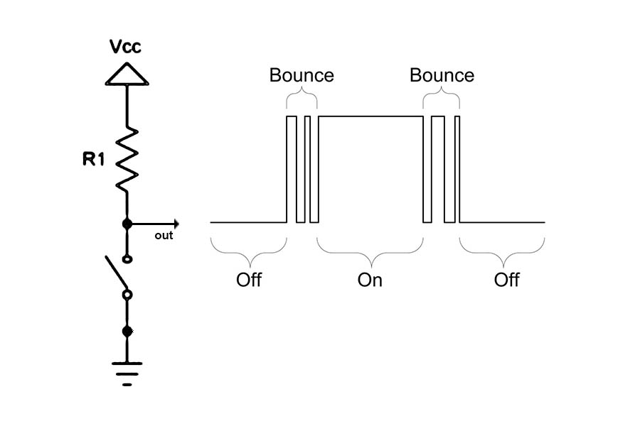
If the switch is used to do is turn on bulbs or start a fan motor, then contact bounce is not a problem. But when a switch is using as input to a digital counter, or a microprocessor-based equipment, then you must consider bounce of switch . The reason is that the time it takes for stop bouncing is measured in milliseconds. Digital circuits can respond in microseconds. So this is cause to change in expected result
Characteristics of switch bounce :-
- all switches do bounce
-the duration of bouncing and the period of each bounce varies
-switches of exactly the same type bounce differently
-bounce differs depending on user force and speed
-typical bounce frequency is .1-5ms
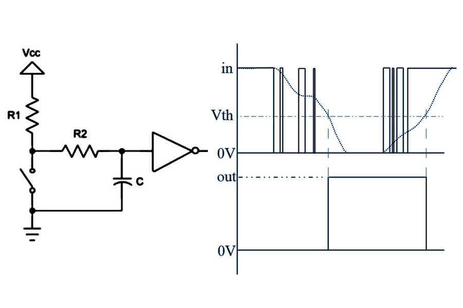
There are many different approaches to cleaning up switch bounce.
Below is a debouncing circuit. The basic idea is using the circuit is a capacitor to filter out any quick changes in the switch signal.
The basic idea of Software Debounce is sample the switch signal at a regular interval and filter out any glitches .A typical debounce routine is given below in a sort of generic assembly language.
DR: PUSH PSW ; SAVE PROGRAM STATUS WORD
LOOP: CALL DELAY ; WAIT A FIXED TIME PERIOD
IN SWITCH ; READ SWITCH
CMP ACTIVE ; IS IT STILL ACTIVATED?
JT LOOP ; IF TRUE, JUMP BACK
CALL DELAY ;
POP PSW ; RESTORE PROGRAM STATUS
EI ; RE-ENABLE INTERRUPTS
RETI ; RETURN BACK TO MAIN PROGRAM
Example code for Debounce using Arduino - https://www.arduino.cc/en/Tutorial/Debounce
In the broadest definition, a sensor is an object whose purpose is to detect events or changes in its environment, and then provide a corresponding output
Phototransistor
In my final project I need a Non-contact position sensor for this first I desired use phototransistor . I start to study about working of the phototransistor. I understand one thing photo transistor is similar to an ordinary bipolar junction transistor except that no base terminal is provided. Instead of base current, the input to the transistor is provided in the form of light.
In the below circuit output voltage changes with light is because the phototransistor lets more current pass when more light shines on it or less current pass with less light
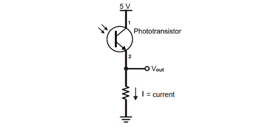
In our fab lab, available OP580 is an NPN silicon phototransistor mounted in a miniature SMD package
![]()
Applications of phototransistor :
Non-contact position sensing
Datum detection
Machine automation
Optical encoder
After studying about photo tram]nsistor I understand one thing it is very difficult to use phototransistor for
detecting the direction of motion in my final project .
The main reason is the output value of the phototransistor varying with respect to surrounding light
IR receiver
I start to study about working of the IR transceivers . I fount that IR transceivers can overcome the limitations of the phototransistor.
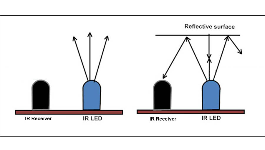
An infrared receiver or IR receiver outputs a code to uniquely identify the infrared signal that it receives.
The IR transmitter LED transmits continuous IR rays , when reflective surface comes near to IR transmitter LED IR rays reflected back . Due to this reflection, the amount of IR rays received by an IR receiver LED is increased . An IR receiver LED output terminal value varies depending upon its amount of receiving of IR rays
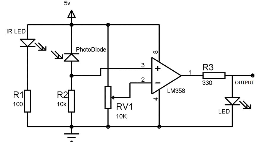
This board is a very important part of my final project . Before starting the design I study about several types of IR modules and IR circuits. Finally I decided to make a modified version of circuit shown in below. Main modification i made on this circuit is replacing LM358 with ATtiny 44 microcontroller and adding two pairs of IR transceivers
Then I star to design the board. In this board I using two IR transceivers used for the movement detection and Attiny 44 micro-controller for processing data from the IR receiver . And two blue color LED one is using for power indication in whole board and another one is for correct movement indication. Draw schematic circuit in eagle show in below
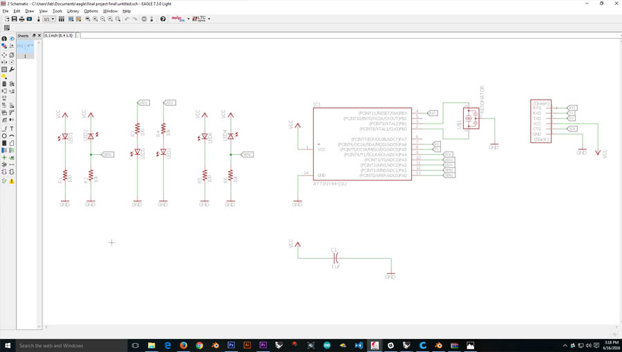
Download Schematic file (.sch)
The designing of the board is very difficult because I wand to include this board into fixed size rectangular case (36mmx17mm) of my final project and position of LEDs must keep in a fixed position
First, I locked LEDs and IR receivers in a fix the position on the board. Then start to arrange the position of other components . I compelled to make a double side design for getting the board in a size what I need
For reducing maximum size In this board both FTDI cable and ISP programmer connecting to FTDI header . for this I set MISO and MOSI to Tx and Rx pin of FTDI header
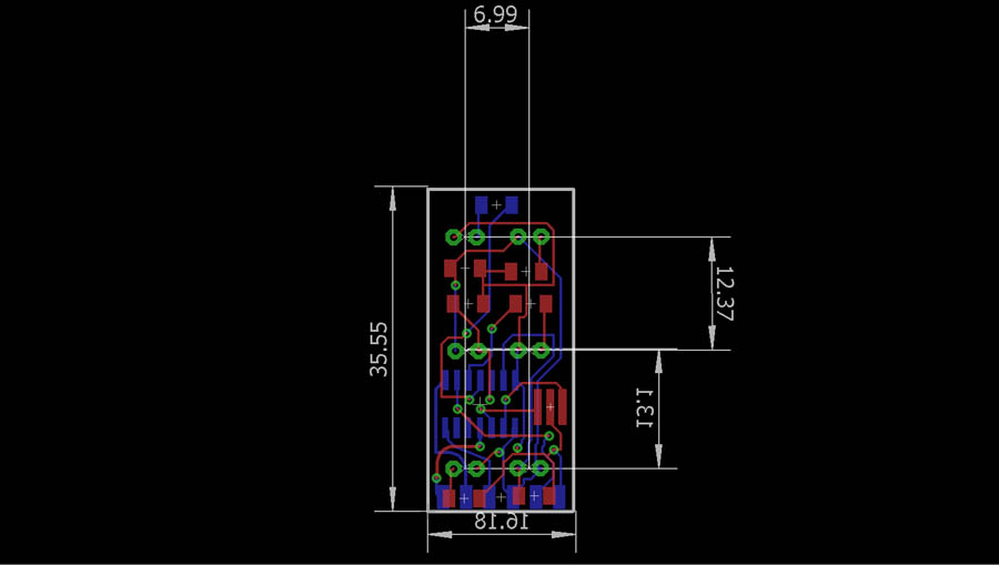
Download Board file (.brd)
Milling&Stuffing the board
Milling double sided PCB :-
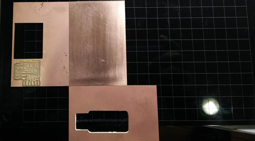
This was the first time I'm doing a double sided board,first, I export all traces , pads and via holes from eagle software into .png format .Shown below
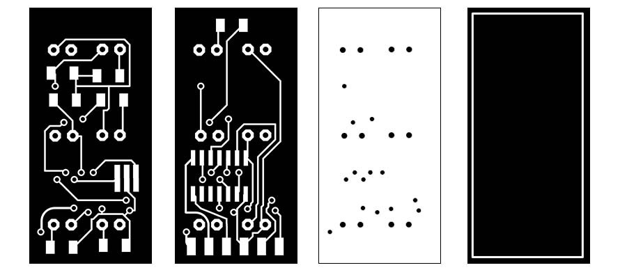
Then I set my PCB to mill with a support of the adjacent side of two waste PCBs(shown below).This setup helps me to maintain PCB in the same position when flip it for mill opposite side
Then started milling my board. I use 1/64 bit for mill the traces . After completing milling of one side traces then I change the bit to 1/32 bit for drill the hole. Then make a change "bottom height" from -1.7 to -0.85 ( half of 1.7) on the "fab module". This value change cause to make the depth of the hole drilled is half copper board . Other half depth drills from another side of the board
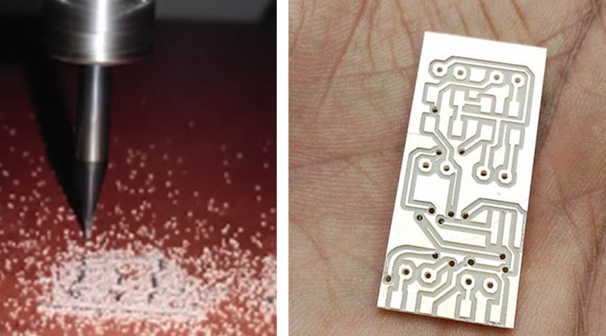
After milling the board I start to stuffing the board . Before soldering the components on the board I interconnect the via in the board, I use narrow copper wires to interconnect vias
I spent a lot of time for interconnecting vias using copper wires this is the riskiest part on this board making . For avoiding short circuit I manually remove unused copper using knife this is helping me to do soldering more easier ( set the offsets to -1 in order to remove all the unused copper during the milling )
After finishing connection of vias I start soldering the components into the board quite fast
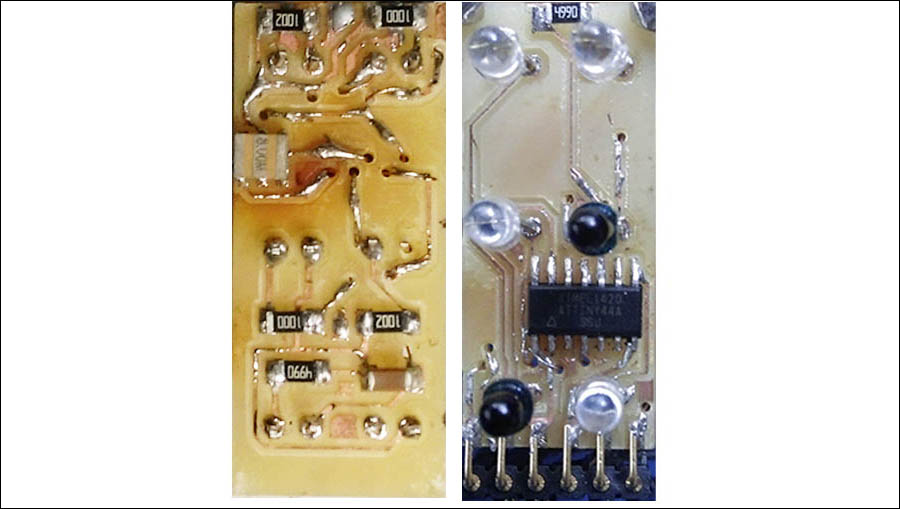
show below the final result of both sides of the board :
------
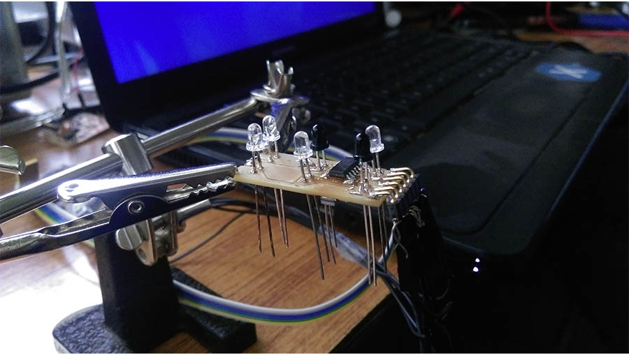
For make connection easier with board I use jumper wires to connect FTDI header of broad , And another end of jumper wires is connected to isp programmer or FTDI cable ( this arrangement helps me to reduce the damage to board during testing )
Programming the board
Obtaining readings from the sensors :-
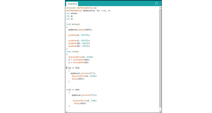
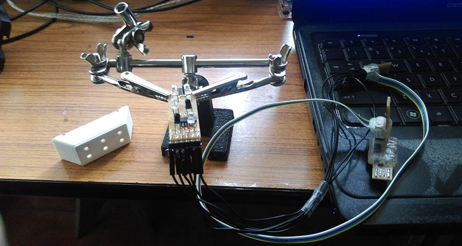
Here I am using two IR transceivers used for the movement detection .For Obtaining maximum and minimum readings from the sensors, connect the board to my computer using FTDI cable. Then continuously read IR receiver value using "analogRead" command in Arduino and use serial monitor to show the range of values. I use the following program to read the values
Using above program I got the maximum value from the sensor "900" ( when the finger very close to the sensor ) and minimum value "0" ( finger away from the sensor )
Then make a program for the finger movement detection . Here I using two IR sensors modules (sensor 1 and sensor 2) , if the finger is first above the sensor 1 input value to microcontroller I/O port of sensor one is 900 and sensor two is 0 , this time sent a string value " Move Left " via FTDI cable vice versa sensor two is 900 and sensor one is 0, this time another sent a sting value " Move Right "
Then I connect fab ISPwirh the board for burn the program
Final result show in video finger is above the sensor 1 set a sting Move Left and finger is above the sensor 2 set a sting Move Right